5.1.1. GPIO
5.1.1.1. 设备节点
目前的方法为上层写入对应设备节点; 设备节点为/sys/devices/platform/1000b000.pinctrl/mt_gpio; 可以进行的常用操作为设为GPIO模式,设置输入/输出,输出高/低。 设置GPIO模式,pin 表示GPIO数(请使用表格里面对应的GPIO数),mode表示GPIO模式(0-6)。
5.1.1.2. 参考代码
private static final String GPIO_DEVICE_PATH = "/sys/devices/platform/1000b000.pinctrl/mt_gpio";

//设置GPIO工作模式;pin表示设置的GPIO口
  protected boolean ZiverSetGpiomode(int mode,int pin) {
        try{
                        File f= new File(GPIO_DEVICE_PATH) ;
                        FileOutputStream out = null ;
                        out = new FileOutputStream(f) ;
                        String str = "mode"+pin+" "+mode+"\n" ;
                        byte b[] = str.getBytes() ;
                        out.write(b) ;
                        out.close() ;
                        return true;
                }
                catch (FileNotFoundException e) {
            Log.e(TAG, "write ZiverSetGpiomode  error:" + e);
        } catch (IOException e) {
            Log.e(TAG, "write ZiverSetGpiomode error:" + e);
        }
                return false;
}

//设置GPIO为输入模式;pin表示设置的GPIO口
    protected boolean ZiverSetGpioInput(int pin) {
        try{
                File f= new File(GPIO_DEVICE_PATH) ;
                FileOutputStream out = null ;
                out = new FileOutputStream(f) ;
                String str = "dir"+pin+" 1\n" ;
                byte b[] = str.getBytes() ;

                out.write(b) ;
                out.close() ;
                return true;
                }
                catch (FileNotFoundException e) {
            Log.e(TAG, "write ZiverSetGpioInput error:" + e);
        } catch (IOException e) {
            Log.e(TAG, "write ZiverSetGpioInput  error:" + e);
        }
                return false;
}

//设置GPIO为输出模式;pin表示设置的GPIO口
    protected boolean ZiverSetGpioOutput(int pin) {
    try{
                        File f= new File(GPIO_DEVICE_PATH) ;
                        FileOutputStream out = null ;
                        out = new FileOutputStream(f) ;
                        String str = "dir"+pin+" 0\n" ;
                        byte b[] = str.getBytes() ;

                         out.write(b) ;
                        out.close() ;
                        return true;
                }
                catch (FileNotFoundException e) {
            Log.e(TAG, "write ZiverSetGpioOutput error:" + e);
        } catch (IOException e) {
            Log.e(TAG, "write ZiverSetGpioOutput error:" + e);
        }
                        return false;
}
//设置GPIO为输出高模式;pin表示设置的GPIO口
    protected boolean ZiverSetGpioDataHigh(int pin) {
         try{
                File f= new File(GPIO_DEVICE_PATH) ;
                FileOutputStream out = null ;
                out = new FileOutputStream(f) ;
                String str = "out"+pin+" 1\n" ;
                byte b[] = str.getBytes() ;

           out.write(b) ;
                out.close() ;
                return true;
                }
                catch (FileNotFoundException e) {
            Log.e(TAG, "write ZiverSetGpioDataHigh error:" + e);
        } catch (IOException e) {
            Log.e(TAG, "write ZiverSetGpioDataHigh error:" + e);
        }
                return false;
}

//设置GPIO为输出低模式;pin表示设置的GPIO口
        protected boolean ZiverSetGpioDataLow(int pin) {
            try{
                         File f= new File(GPIO_DEVICE_PATH) ;
                    FileOutputStream out = null ;
                    out = new FileOutputStream(f) ;
                    String str = "out"+pin+" 0\n" ;
                    byte b[] = str.getBytes() ;
                    out.write(b) ;
                    out.close() ;
                        return true;
                }
                catch (FileNotFoundException e) {
            Log.e(TAG, "write ZiverSetGpioDataLow error:" + e);
        } catch (IOException e) {
            Log.e(TAG, "write ZiverSetGpioDataLow error:" + e);
        }
                        return false;
}
//设置GPIO为内部上拉模式;pin表示设置的GPIO口
    protected boolean ZiverSetGpioPullen(int pin) {
        try{
                File f= new File(GPIO_DEVICE_PATH) ;
                FileOutputStream out = null ;
                out = new FileOutputStream(f) ;
                String str = "pullen"+pin+" 1\n" ;
                byte b[] = str.getBytes() ;

                out.write(b) ;
                out.close() ;
                return true;
                }
                catch (FileNotFoundException e) {
            Log.e(TAG, "write ZiverSetGpioPullen error:" + e);
        } catch (IOException e) {
            Log.e(TAG, "write ZiverSetGpioPullen  error:" + e);
        }
                return false;
    }
//设置GPIO为内部不上拉模式;pin表示设置的GPIO口
    protected boolean ZiverSetGpioPulldisable(int pin) {
    try{
                        File f= new File(GPIO_DEVICE_PATH) ;
                        FileOutputStream out = null ;
                        out = new FileOutputStream(f) ;
                        String str = "pullen"+pin+" 0\n" ;
                        byte b[] = str.getBytes() ;

                         out.write(b) ;
                        out.close() ;
                        return true;
                }
                catch (FileNotFoundException e) {
            Log.e(TAG, "write ZiverSetGpioPulldisableerror:" + e);
        } catch (IOException e) {
            Log.e(TAG, "write  ZiverSetGpioPulldisableerror:" + e);
        }
                        return false;
}

//设置GPIO为内部拉高模式;pin表示设置的GPIO口
    protected boolean ZiverSetGpioPullHigh(int pin) {
         try{
                File f= new File(GPIO_DEVICE_PATH) ;
                FileOutputStream out = null ;
                out = new FileOutputStream(f) ;
                String str = "pullsel"+pin+" 1\n" ;
                byte b[] = str.getBytes() ;

           out.write(b) ;
                out.close() ;
                return true;
                }
                catch (FileNotFoundException e) {
            Log.e(TAG, "write  error:" + e);
        } catch (IOException e) {
            Log.e(TAG, "write  error:" + e);
        }
                        return false;
      }

//设置GPIO为内部不上拉模式;pin表示设置的GPIO口
protected boolean ZiverSetGpioPullLow(int pin) {
            try{
                         File f= new File(GPIO_DEVICE_PATH) ;
                    FileOutputStream out = null ;
                    out = new FileOutputStream(f) ;
                    String str = "pullsel"+pin+" 0\n" ;
                    byte b[] = str.getBytes() ;
                    out.write(b) ;
                    out.close() ;
                        return true;
                }
                catch (FileNotFoundException e) {
            Log.e(TAG, "write error:" + e);
        } catch (IOException e) {
            Log.e(TAG, "write error:" + e);
        }
                        return false;
        }
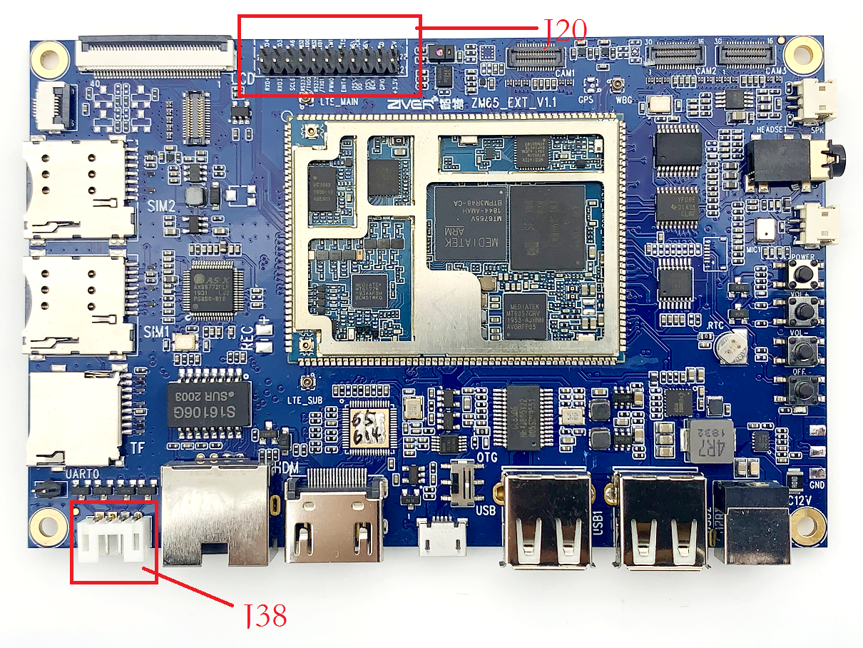
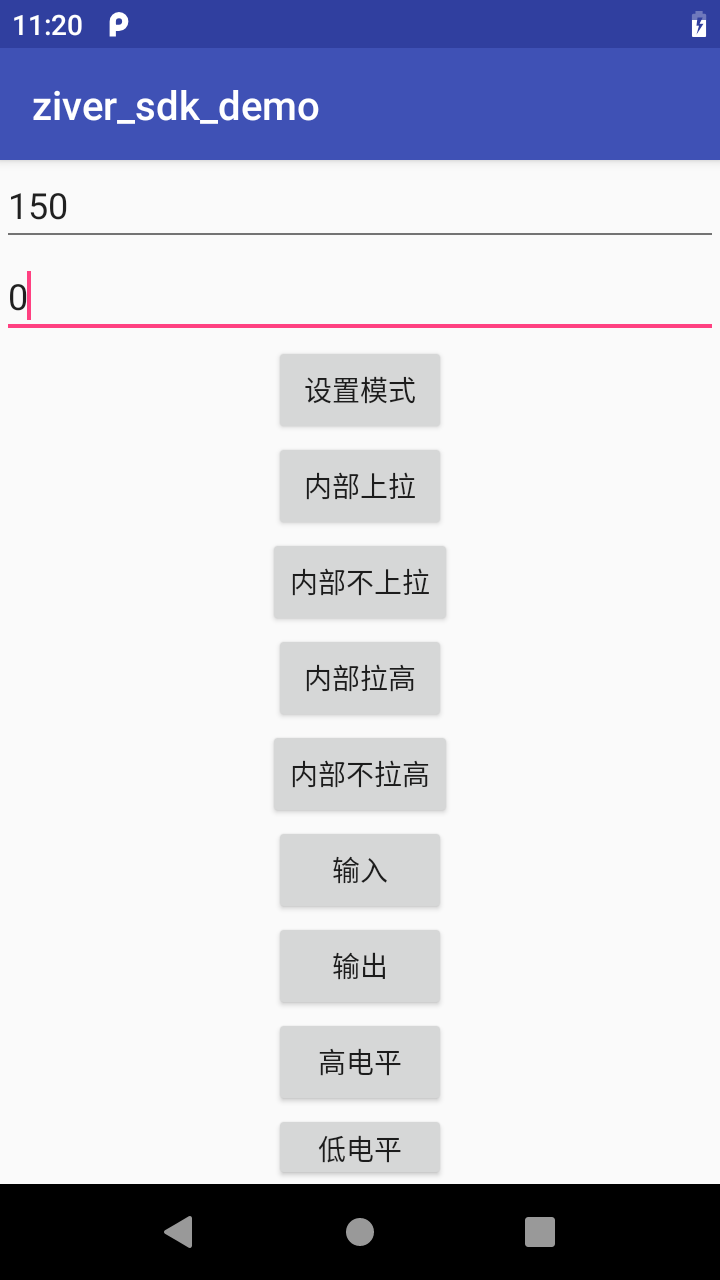
其中mode为0-6,pin为GIPO列的数值。 对应我们开发板开放的GPIO在J20上。 其中的对应关系如下表: 比如设置11PIN为GPIO就调用ZiverSetGpiomode(150,0);
5.1.1.3. GPIO相关PIN定义
请注意使用的时候控制正确的脚:一般客户只操作150 、151、 42; J20位置如下:

| J20 | 丝印名字 | GPIO |Aux Func.1 | Aux Func.2 | |
|---|---|---|---|---|
| 11 | PWM0 | GPIO150|B:GPIO150 | O:PWM0 | |
| 12 | PWM1 | GPIO151|B:GPIO151 | O:PWM1 | |
| 19 | GPIO(DRVBUS) | GPIO42 |B:GPIO42 | ||
5.1.1.4. APK演示
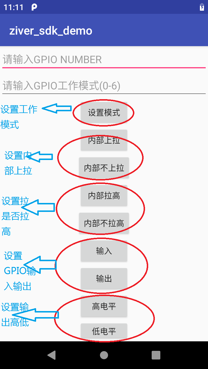
APK演示如下图: GPIO如果作为GPIO,输出方向 一般只控制IO方向(输出、输入),输出的话有高低之分, 输入的话需要去检测这个口状态,目前SDK不支持; GPIO作为PWM,只需要设置mode,输出高就可以。同时需要去配置PWM频率和占空比这些。这部分如果有需求请联系我们


