3.1.5. UART
ZM65 4G Mini板有2个UART。其中在deviceInit()中id对应0-1; 0-1对应/dev/ttyS0,/dev/ttyS1,为系统自带的UART,/dev/ttyS0默认为调试串口。 UART 0-1在硬件J21上;
3.1.5.1. UART硬件接口定义
J21的位置如下:
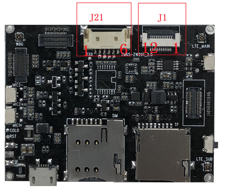
硬件接口如下:
UART 0-1在硬件J21上;
| J38 | 丝印名字 | 对应设备节点 |
|---|---|---|
| 1 | D3V3 | 对外3.3V供电 |
| 2 | UTXD0 | /dev/ttyS0 |
| 3 | URXD0 | |
| 4 | UTXD1 | /dev/ttyS1 |
| 5 | URXD1 | |
| 6 | GND | GND |
此时信号为1.8V TTL信号。
如果有贴U24;
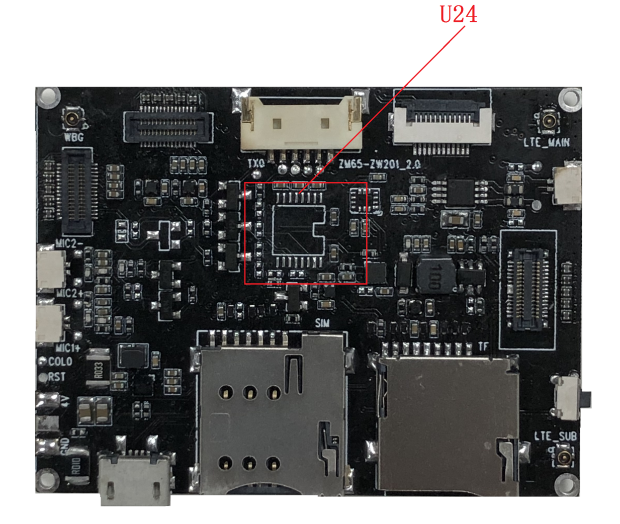
此时信号为3.3V RS232信号。
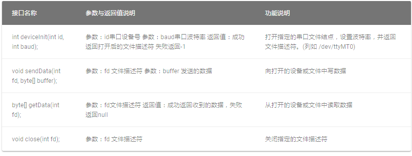
3.1.5.2. UART的Native申明方法
UART的native申明如下,注意class路径:
package com.ziver.Native;
public class UART {
    static public native int deviceInit(int id, int baud);
    static public native void sendData(int fd, byte[] buffer);
    static public native byte[] getData(int fd);
    static public native void close(int fd);
}

